Chapter 2 How to Connect
This chapter contains the following sections :
• Lightning and ESD Protection
Installation
- Please follow the installation steps when assembling the device.
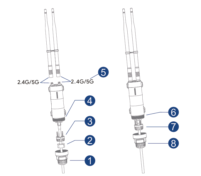
① Pass RJ45 cable through the spiral cover.
② Pass RJ45 cable through the rubber seal.
③ Pass RJ45 cable through the holder.
④ Connect the RJ45 cable to RJ45 port.
⑤ Spin 2.4G/5G antenna into the 2.4G/5G external RP-SMA connector.
⑥ Plug the holder.
⑦ Plug the rubber seal to the holder.
⑧ Screw up the spiral cover.
2.Outdoor Installation
Fix the device to the pole with cable ties, or fix the device to the wall with screws.
1.1 Pole Mounting
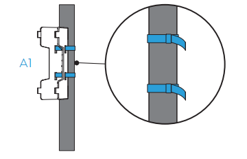
Step 1. Fasten the main body holder to the pole with two cable ties.
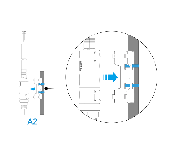
Step 2. Plug the AP into the holder.
Remark
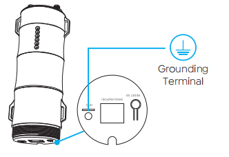
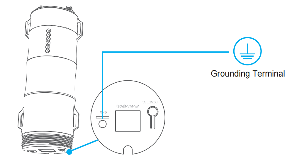
If you happen to live in the zone where lightning happens a lot, we suggest that you install the device through grounding connection in order to strengthen the lightning-resistant function.
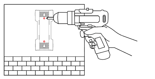
1.2 Wall Mounting Step 1.Attach the holder onto the wall, then use the drill to make two holes on the wall at the position designated by the holes from the body holder.
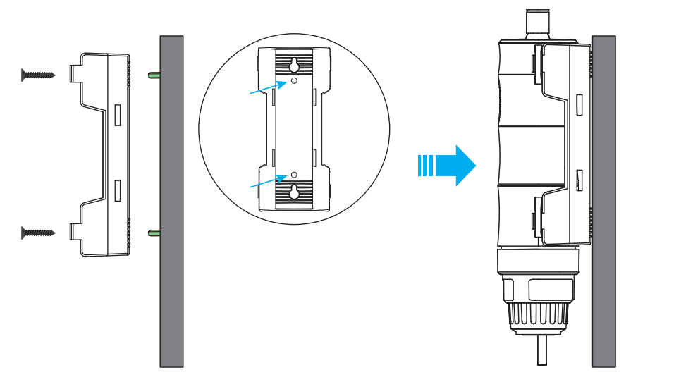
Step 2. Insert the screws into the holes.

Step 3. Fix the body holder to the wall using screws, then plug the AP into the holder.
Connection
Passive PoE
(1) Wired (For AP/Router Mode)
 (2) Wireless (For Repeater Mode)
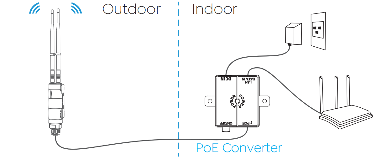
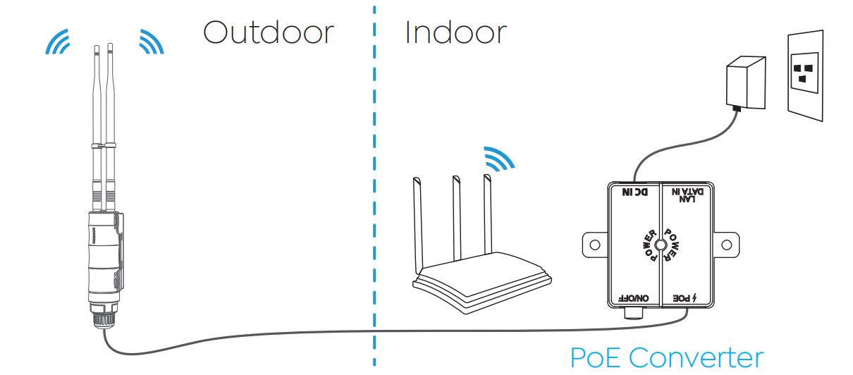 ① Connect the “PoE” port of the PoE converter with an Ethernet cable to the “WAN/LAN Port” of the device.
② Connect the PoE converter to power source.
③ Connect the indoor router to PoE converter via an Ethernet cable for AP/Router mode, or wirelessly for Repeater mode.
Note: The PoE converter is not waterproof. Please place the “PoE” port facing downwards to avoid water from flowing into the converter.
Active PoE (For AP/Router Mode)
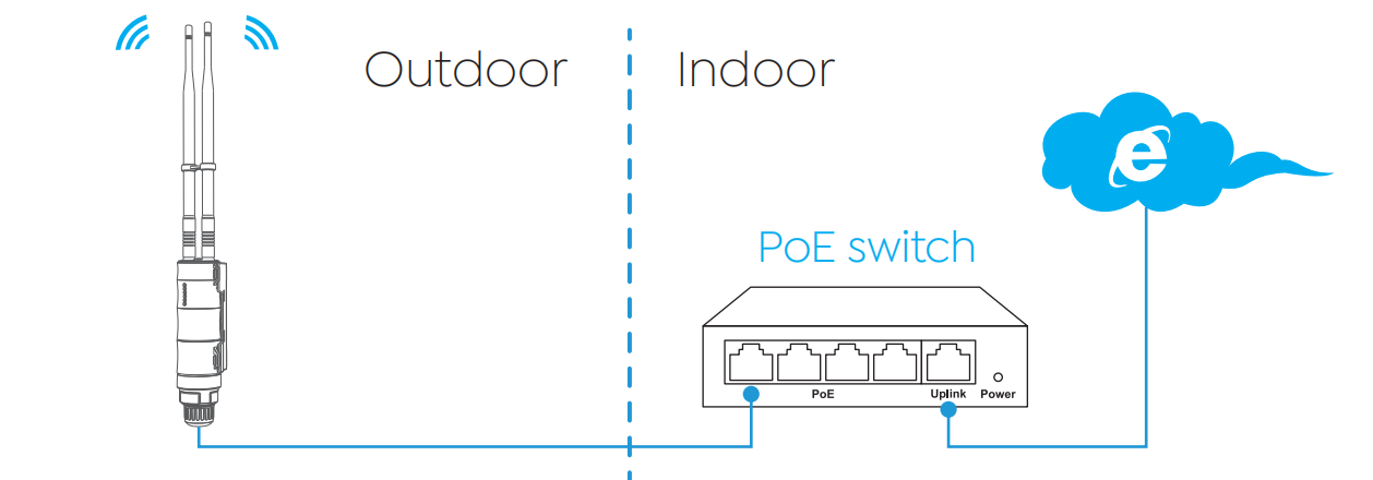 Attention:
① Make sure you use a certified CAT5 or higher standard Ethernet cable with RJ45 connectors.
Attention:
① Make sure you use a certified CAT5 or higher standard Ethernet cable with RJ45 connectors.
Configuration
Connecting to the Network
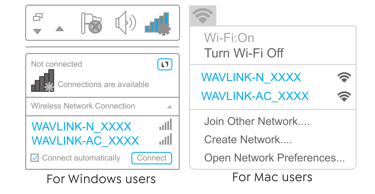
Wireless Connection
- Disconnect the Ethernet cable from your computer(if you have one).
- Turn on your WiFi, find the SSID of this product on your wireless devices(smartphone, tablet computer, laptop, etc.) and place a connection.
Wired Connection
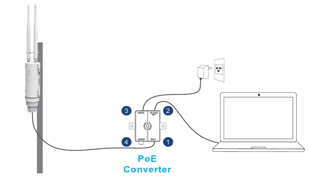
- Connect the Ethernet cable to your PC/laptop and the LAN DATA IN port of your PoE converter, and then you can start configuring the device.
The above steps are the operations for the FAT AP mode. For the operation of FIT AP mode, please go to FAT AP and FIT AP for the details.
If you plan to use the AP/Router function of this device:
After completing the initial mode configuration, please connect the LAN DATA IN port of this device to a LAN port on your main upper router.
FAT AP and FIT AP
This product supports FAT AP and FIT AP mode. In FAT mode, the AP operates with its own management interface and can be configured independently, similar to a standard wireless access point; this mode is primarily employed in small-scale networks that do not use an AC controller.
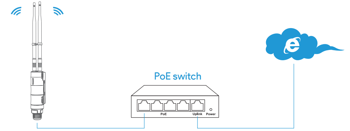
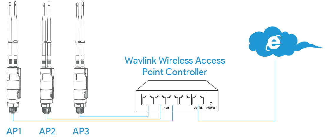
In FIT mode, the AP is centrally managed by a WAVLINK AC(Wireless Access Point Controller). As a Fit AP, it primarily handles data transmission and basic radio frequency, while all network configurations, security policies, and traffic controls are managed by the AC. Fit APs are used in an AC+AP architecture and must operate in conjunction with a WAVLINK AC. FIT mode is ideal for larger networks characterized by extensive coverage, a high density of users, and requirements for high-performance and secure operations.
Setting up the Device
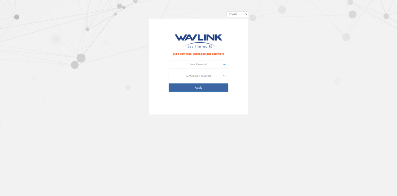
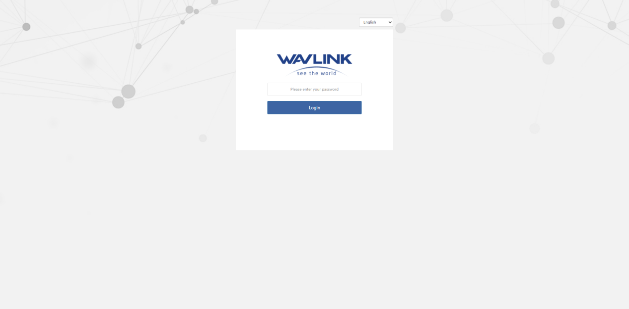
The login page will pop up when the router is connected to your devices for the first time. You can also launch a browser from your computer or smartphone and enter 192.168.10.1 or http://waplogin.link into the address bar(not search bar). Please set a new local management password, then enter it to log in.
Mode Selection
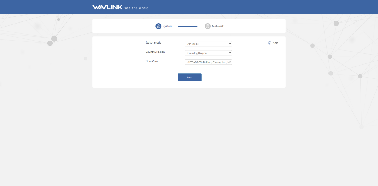
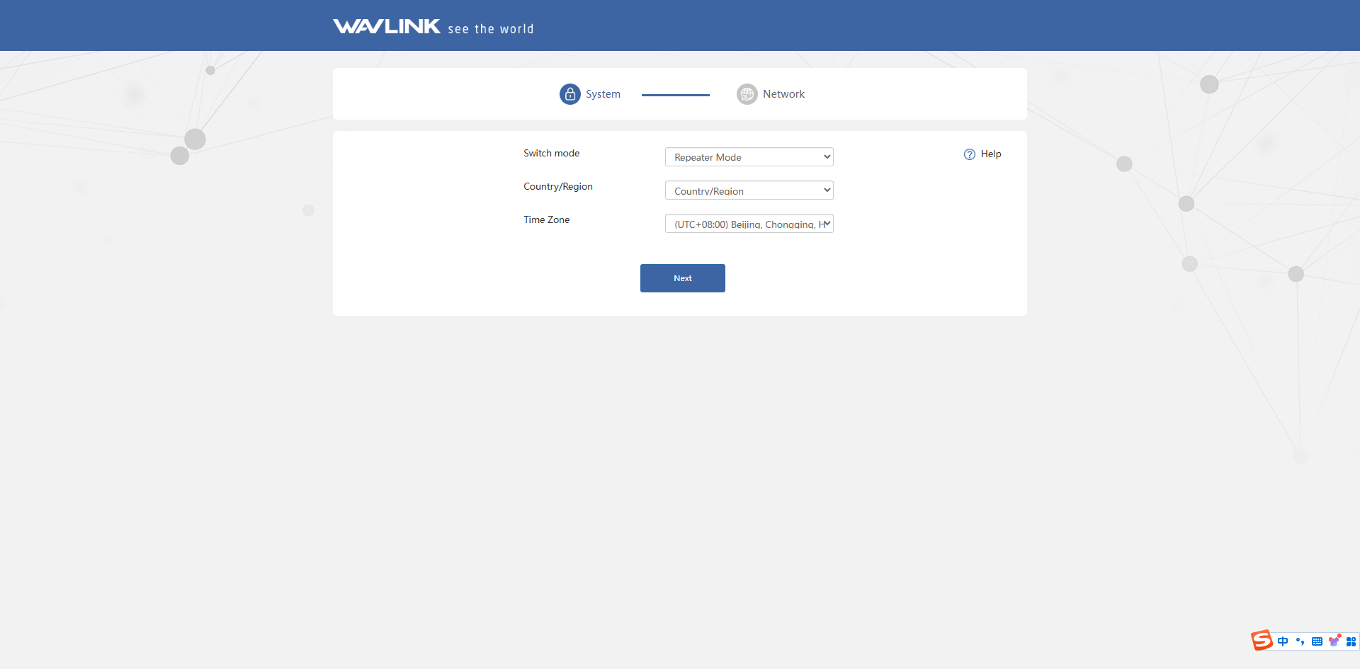
This product supports 3 modes. Click Switch mode to select corresponding mode. The system selects AP mode by default. Select your Country/Region and Time Zone.
AP Mode
The purpose of AP mode: AP mode can help you convert existing wired signals into wireless signals.

- The system selects AP mode by default, there is no need to select the AP mode manually. Click on Next.
- Connect the WAN/LAN port of this product to the PoE and connect the LAN DATA IN port of the poe box to the host router via Ethernet cable.
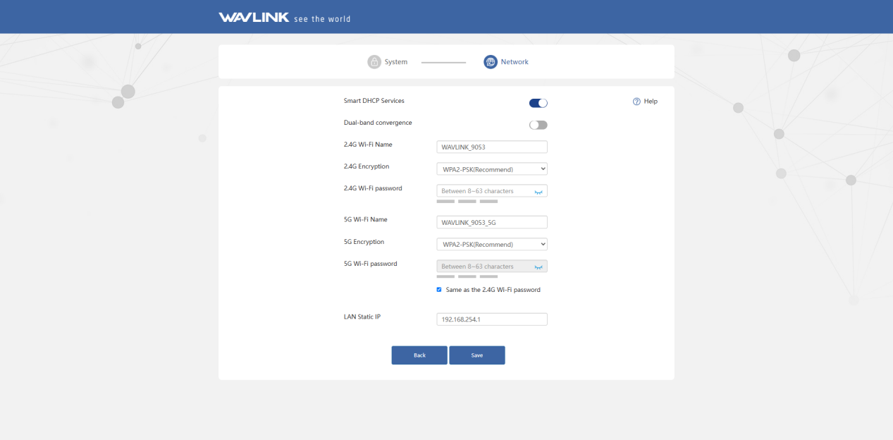
- Then you can change the SSID, the encryption mode recommend is WPA2-PSK. For your network security, please create a new Password according to the rule. Then click on Save and wait for the setting process to complete.
Note
- For Smart DHCP Service: With smart DHCP service being enabled, if the upstream device is not been connected or the upstream device is unable to provide IP, the router will assign the IP automatically. If no automatical IP assignment is needed, it is recommended to disable it.
- After configuration in AP mode. To log in the management page again, please connect the WiFi signal of WAVLINK device and use http://waplogin.link to log in.(http://192.168.10.1 might not work)
Router Mode
The purpose of router mode: Router mode can help you convert existing wired signals to wireless signals,supports wired connections, Wi-Fi networking, and internet sharing among multiple devices.
-
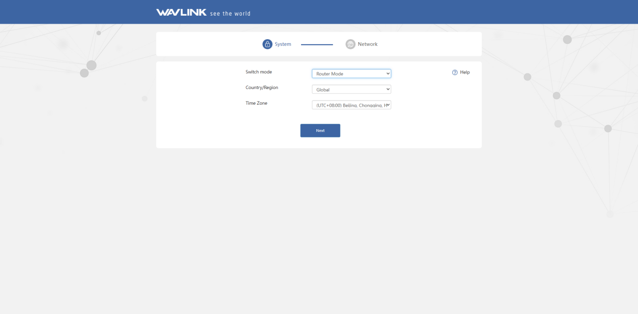
Select Router Mode.
-
Choose Router Mode, configuring the corresponding WAN Type, SSID(Wi-Fi name), Encryption Method and Password, then click Save.
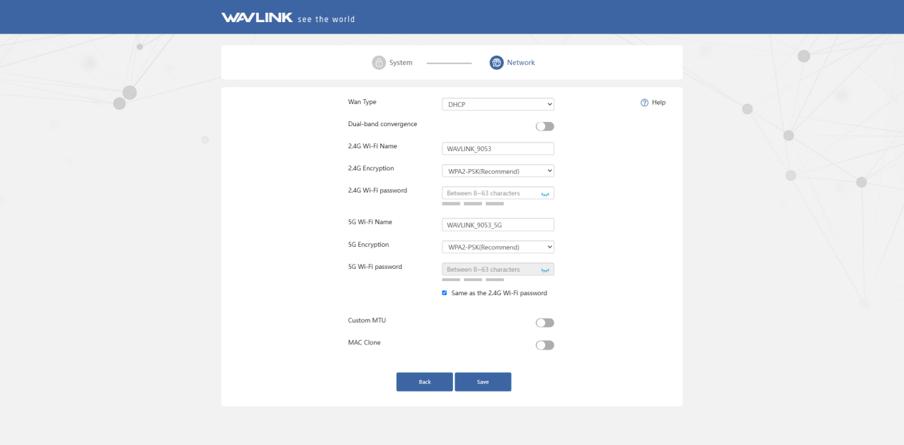
① If you choose DHCP, you will need to decide whether to enable the MAC clone. Some ISPs register the MAC address of your computer when you firstly access the Internet through their cable modem, we need to clone the MAC address of your computer to the router. The Custom MTU(Maximum Transmission Unit) is the largest size of a data packet that can be transmitted over the network. If your ISP requires you to adjust the MTU size, enable this option. Otherwise, we recommend you to keep it disabled for optimal network performance.
② If you choose PPPoE, enter the Username and Password provided by your ISP. PPPoE is usually designed for such as DSL or fiber optics.
③ If you choose Static IP, enter a specified IP parameters including IP address, Subnet Mask, Gateway, DNS1 and DNS2 provided by your ISP.
Repeater Mode
The purpose of repeater mode: In repeater mode, the WAVLINK device can establish a wireless connection with the upstream router. And it will create one or two new WiFi signals to cover a larger area.
- Select Repeater Mode.
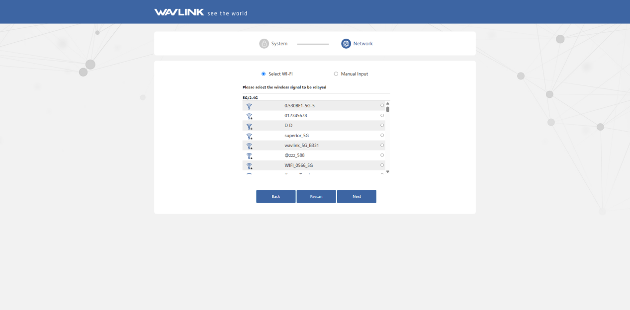
Select Wi-Fi
- After scanning, please make sure the Wi-Fi you want to select is listed, and click Next, if it isn't, please click Rescan.
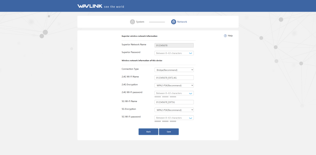
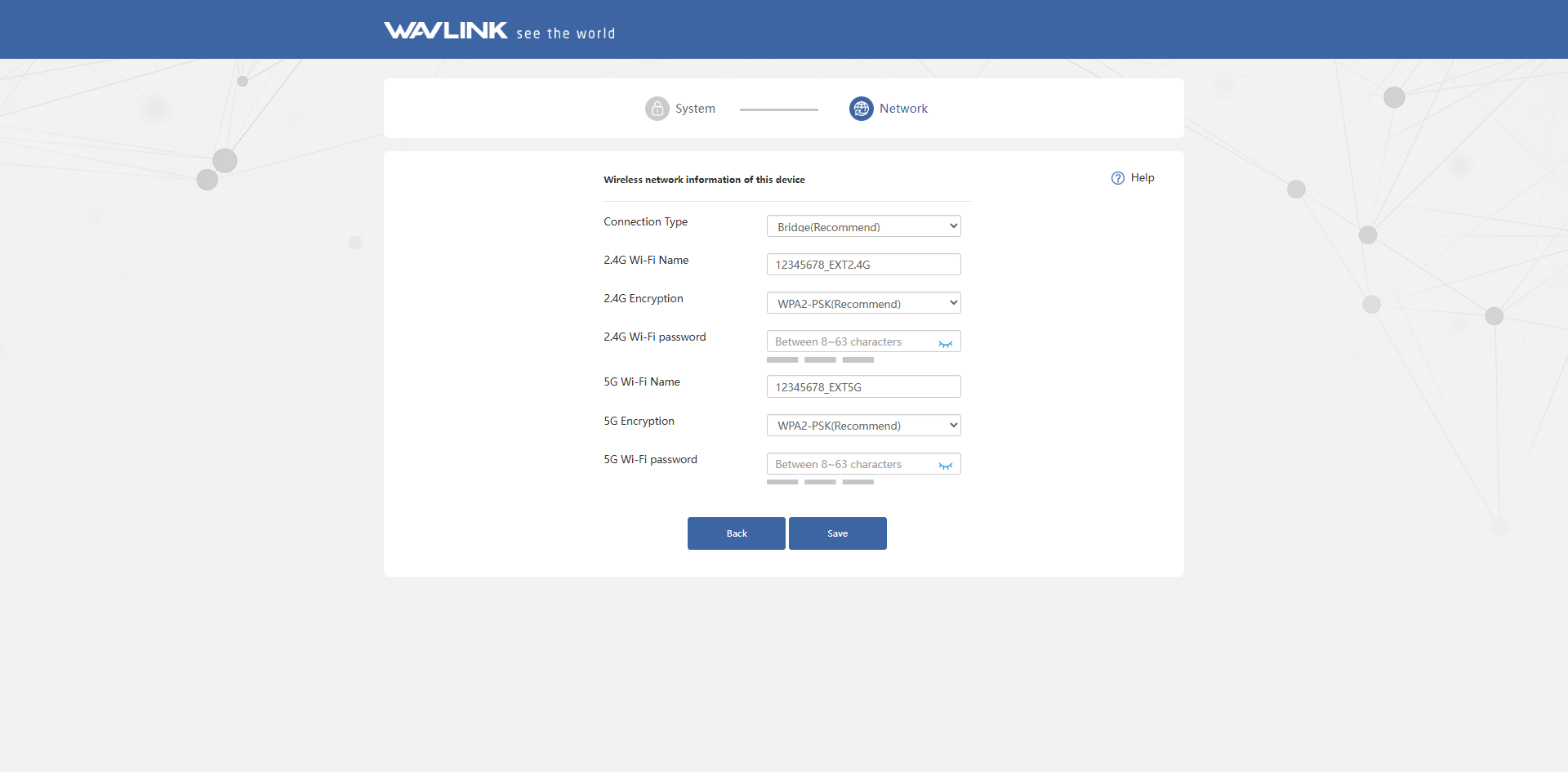
- Set the wireless network encryption method and password for this device. Click Save.
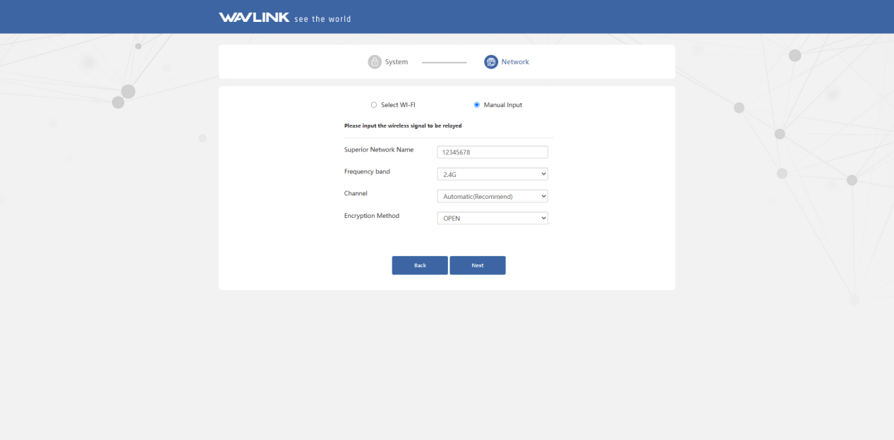
Manual Input
If the WiFi signal of the upstream router is hidden, you could enter its WiFi name manually.
- Manually add the wireless network you want to connect, enter the device information, and click Next.
- Set the wireless network encryption method and password for this device. Click Save.
Lightning and ESD Protection
It is recommended to install a grounding wire to enhance the equipment's protection against lightning and static electricity, thereby ensuring the product's service life, please use a suitable grounding wire to connect the grounding terminal to the grounding facility before installing this product. And the grounding wire should meet the local installation requirements. You should use screws to secure the grounding wire to the grounding terminal.